Repeated Loading and Unloading
Removing, moving, and feeding every workpiece again adds handling time between the two faces.
Move wood doors, cabinet panels, and furniture components through first-side sanding, automatic 180-degree turning, second-side sanding, and collection in one connected flow.
For factories running repeat double-sided work, fewer handoffs can support a steadier rhythm. Station scope is matched to the workpiece, finish stage, output target, floor space, and existing equipment.
If two sanding passes are separated by repeated handling, the delay between them can become the real constraint—not the sanding speed.
Removing, moving, and feeding every workpiece again adds handling time between the two faces.
A manual 180-degree turn interrupts the flow before every second-side pass.
Separate sanding, transfer, turning, and collection stages make it harder to keep upstream and downstream equipment at the same rhythm.
A defined daily or shift target shows whether the current route still has enough production headroom.
Loading, turning, and two sanding passes stay connected in one material flow.
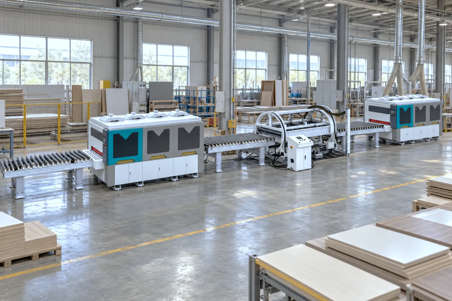
Raises the incoming workpiece stack to feeding height.
Feeds each workpiece into the first sanding station.
Processes the first face to the confirmed finish requirement.
Turns the workpiece inside the line for the opposite-face pass.
Processes the opposite face without returning to the first station.
Receives the finished workpiece for the next factory operation.
With the same workpiece and operating assumptions, the linked-line reference reaches approximately 786 panels per day—about 100% above the single-machine reference of approximately 393 panels per day.
The gain comes from planning both sanding passes, the 180-degree turn, and transfer as one sequence, so the workpiece does not return to the first station for its second face.
Reference conditions
Project output depends on the workpiece, loading method, station balance, process requirements, and planned operating conditions.
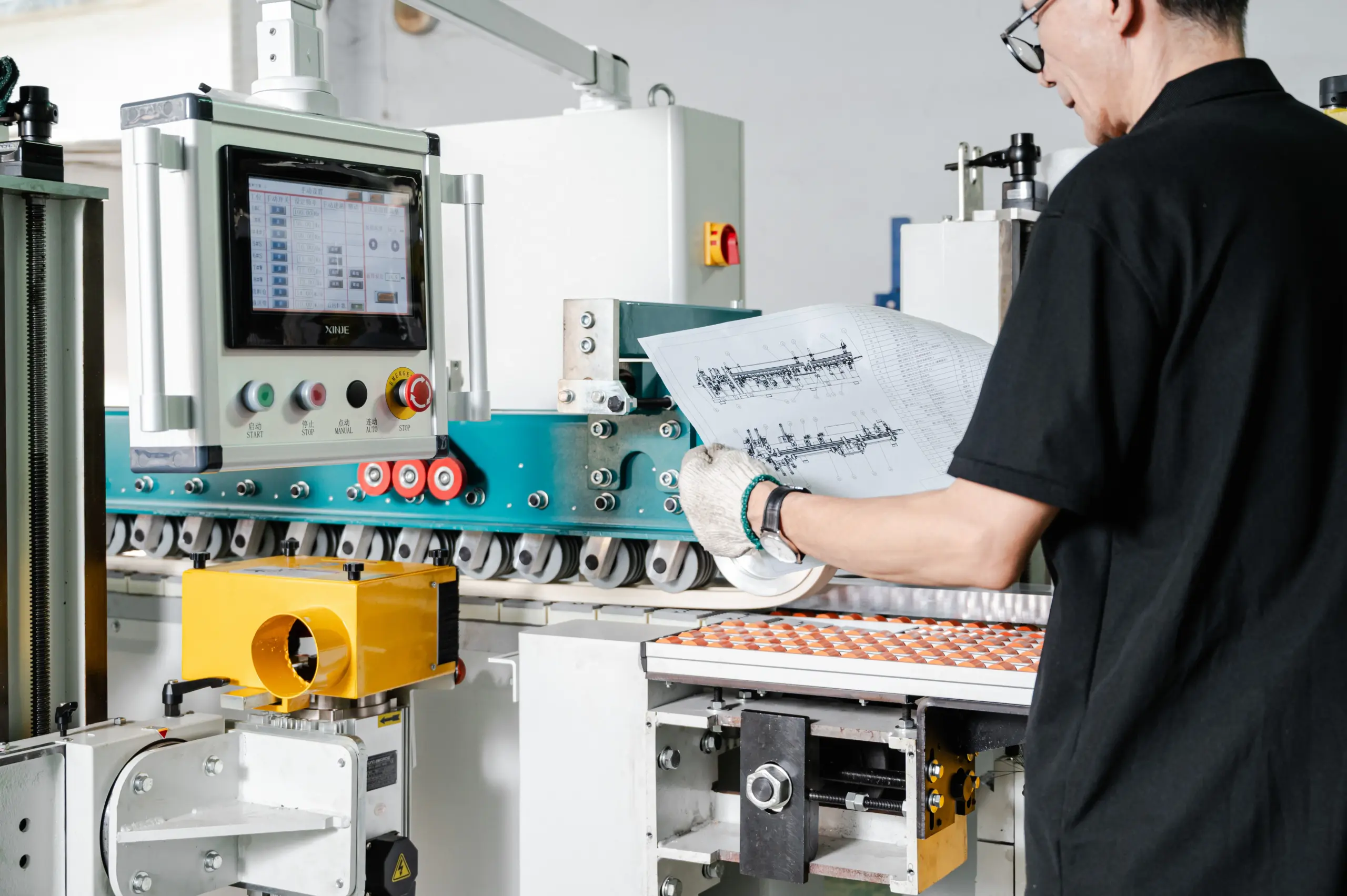
MASA converts the confirmed workpiece and process requirements, output target, shift plan, and floor space into a project-specific line configuration.
MASA matches the station sequence and machine combination to the workpiece geometry, finish stage, and required output.
Send the workpiece material, size range, surfaces, finish stages, output target, working hours, floor dimensions, and connected-equipment constraints.
MASA can prepare an initial layout in about 3–5 days once the process and output information is complete, showing station order, equipment placement, and material-flow direction.
Before production, MASA confirms the complete line configuration, including station sequence, machine combination, material-flow stations, transfer interfaces, factory layout, applicable machine-level presets, and material-test requirements.
Automated line projects typically require 45–60 days from deposit receipt, depending on the confirmed layout and equipment mix.
Before shipment, MASA checks voltage, leakage protection, appearance, and machine functions using supplied project material and configured presets. Video and onsite factory inspection are supported.
Installation support can include video guidance, English illustrated manuals, and onsite engineer support for larger customers.
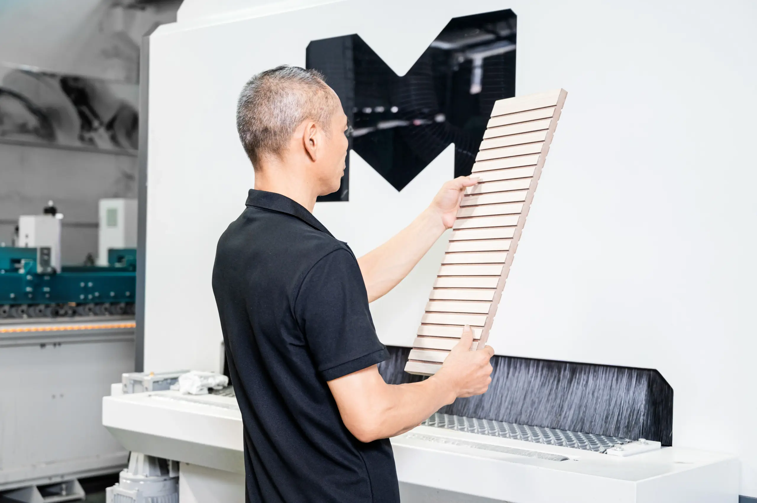
A linked line is worth closer review when several of these production signals appear together:
This production picture allows a direct comparison between a standalone-machine route and a linked line before the equipment scope is defined.
Send the workpiece material, dimensional range, surfaces, finish stages, target output, working hours, factory dimensions, and details of existing upstream or downstream equipment.
Attach a floor plan, workpiece photos, or drawings where available. The review will cover material flow, station scope, capacity assumptions, machine-level preset requirements, and the pre-shipment test plan.